1
More Annotations


1


6
Favourite Annotations


2


5
Text
CHANNELIZATION
Channelization. Consider a network in which the M stations that are sharing a medium produce the same steady rate of information, for example, digital voice or audio streams. It then makes sense to divide the transmission medium into M channels that can be allocated for the transmission of information from each station. In this section wefirst
ASYNCHRONOUS VS SYNCHRONOUS VS ISOCHRONOUS There are two ways to perform the timing for bit synchronization: with an internal clock, or wristwatch, in each device or with an external clock, or wall clock. Asynchronous transmission uses the wristwatch (internal clock) in every device. Synchronous transmission uses the wall clock (external clock). A wall clock works as the analogy here CONCLUSION AND FUTURE WORK Conclusion And Future Work. Through a series of experiments and measurements made at various locations of the AUT's WY office building, we gained an insight into the performance of Wi-Fi links in an office environment. This project involves both literature review and practical investigation regarding the IEEE 802.11b protocol knownas Wi-Fi.
SUPERVISORY LINE SIGNALING Supervisory Line Signaling. 7.3.2.1.1 Introduction. Line signaling on wire trunks was based essentially on the presence or absence of dc current. Such dc signals are incompatible with FDM equipment where the voice channel does not extend to 0 Hz. Remember the analog voice channel occupies the band from 300 to 3400 Hz. UNDERSTANDING THE LLC HEADER GENERAL ARCHITECTURE OF THE PSTN Figure 3.1 depicts the general architecture of the PSTN. Figure 3.1 depicts the general architecture of the PSTN. Inter-Toll Trunks toOther Toll Tandem
MAXIMUM SUBSCRIBER LOOP FORMULA Rt 1250 L = lid:=8222 = 1484 km. Maximum permissible loop length. The method of determing the maximum subscriber loop length using the attenuation or loop loss is called the basic transmission design, the maximum loop length is calculated from the formula. Example 3.5. For 24 gauge loop and a 6 dB loss, find the maximum loop length. SUBSCRIBER SIGNALING Figure 3.1-1 shows the signaling for an intraexchange call between subscribers S1 and S2. The directory number of called subscriber S2 is 347-9654. Calling subscriber Si starts by going off-hook (lifting the handset of the telephone from its cradle). The off-hook is interpreted by the exchange as a request-for-service (a call origination, or TRANSMISSION EFFICIENCY OF ARQ PROTOCOLS The transmission efficiency of Stop-and-Wait ARQ is given by the ratio R^f to R: R i ^ na '2 (tprop H" tproc)R. The preceding equation identifies clearly the sources of inefficiency in transmission. In the numerator the ratio n0/nf represents the loss in transmission efficiency due to the need to provide headers and CRC checks. RECEIVER THERMAL NOISE THRESHOLD 2.6.3.1 Objective and Basic Calculation. One waypoint objective in the path analysis is to calculate the unfaded carrier-to-noise ratio (C/N). With the RSL determined from Section 2.6.2 and with the receiver thermal noise threshold, we can simply calculate the C/N, where. where Pt is the receiver thermal noise threshold. Note that RSL and Pt must be in the same units, conventionally in dBm or dBW.CHANNELIZATION
Channelization. Consider a network in which the M stations that are sharing a medium produce the same steady rate of information, for example, digital voice or audio streams. It then makes sense to divide the transmission medium into M channels that can be allocated for the transmission of information from each station. In this section wefirst
ASYNCHRONOUS VS SYNCHRONOUS VS ISOCHRONOUS There are two ways to perform the timing for bit synchronization: with an internal clock, or wristwatch, in each device or with an external clock, or wall clock. Asynchronous transmission uses the wristwatch (internal clock) in every device. Synchronous transmission uses the wall clock (external clock). A wall clock works as the analogy here CONCLUSION AND FUTURE WORK Conclusion And Future Work. Through a series of experiments and measurements made at various locations of the AUT's WY office building, we gained an insight into the performance of Wi-Fi links in an office environment. This project involves both literature review and practical investigation regarding the IEEE 802.11b protocol knownas Wi-Fi.
SUPERVISORY LINE SIGNALING Supervisory Line Signaling. 7.3.2.1.1 Introduction. Line signaling on wire trunks was based essentially on the presence or absence of dc current. Such dc signals are incompatible with FDM equipment where the voice channel does not extend to 0 Hz. Remember the analog voice channel occupies the band from 300 to 3400 Hz. UNDERSTANDING THE LLC HEADER GENERAL ARCHITECTURE OF THE PSTN Figure 3.1 depicts the general architecture of the PSTN. Figure 3.1 depicts the general architecture of the PSTN. Inter-Toll Trunks toOther Toll Tandem
MAXIMUM SUBSCRIBER LOOP FORMULA Rt 1250 L = lid:=8222 = 1484 km. Maximum permissible loop length. The method of determing the maximum subscriber loop length using the attenuation or loop loss is called the basic transmission design, the maximum loop length is calculated from the formula. Example 3.5. For 24 gauge loop and a 6 dB loss, find the maximum loop length. SUBSCRIBER SIGNALING Figure 3.1-1 shows the signaling for an intraexchange call between subscribers S1 and S2. The directory number of called subscriber S2 is 347-9654. Calling subscriber Si starts by going off-hook (lifting the handset of the telephone from its cradle). The off-hook is interpreted by the exchange as a request-for-service (a call origination, or TRANSMISSION EFFICIENCY OF ARQ PROTOCOLS The transmission efficiency of Stop-and-Wait ARQ is given by the ratio R^f to R: R i ^ na '2 (tprop H" tproc)R. The preceding equation identifies clearly the sources of inefficiency in transmission. In the numerator the ratio n0/nf represents the loss in transmission efficiency due to the need to provide headers and CRC checks. RECEIVER THERMAL NOISE THRESHOLD 2.6.3.1 Objective and Basic Calculation. One waypoint objective in the path analysis is to calculate the unfaded carrier-to-noise ratio (C/N). With the RSL determined from Section 2.6.2 and with the receiver thermal noise threshold, we can simply calculate the C/N, where. where Pt is the receiver thermal noise threshold. Note that RSL and Pt must be in the same units, conventionally in dBm or dBW. GENERAL ARCHITECTURE OF THE PSTN Figure 3.1 depicts the general architecture of the PSTN. Figure 3.1 depicts the general architecture of the PSTN. Inter-Toll Trunks toOther Toll Tandem
SUPERVISORY LINE SIGNALING Supervisory Line Signaling. 7.3.2.1.1 Introduction. Line signaling on wire trunks was based essentially on the presence or absence of dc current. Such dc signals are incompatible with FDM equipment where the voice channel does not extend to 0 Hz. Remember the analog voice channel occupies the band from 300 to 3400 Hz. SUBSCRIBER SIGNALING Figure 3.1-1 shows the signaling for an intraexchange call between subscribers S1 and S2. The directory number of called subscriber S2 is 347-9654. Calling subscriber Si starts by going off-hook (lifting the handset of the telephone from its cradle). The off-hook is interpreted by the exchange as a request-for-service (a call origination, or UNDERSTANDING THE LLC HEADER Understanding the LLC header. To multiplex higher-level protocol data over the wireless link, 802.11 uses the LLC SNAP encapsulation. (SNAP encapsulation was described at the end of Chapter 3.) 802.11 does not include a protocol field, so receivers cannot discriminate between different types of network protocols. PHASE DIVISION MULTIPLEXING Phase Division Multiplexing. The term phase describes the position of the waveform relative to time zero. If we think of the wave as something that can be shifted backward or forward along the time axis, phase describes the amount of that shift. It indicates the status ofthe first cycle.
KEY FACTORS IN COMMUNICATION NETWORK EVOLUTION Before proceeding with the technical details of networking, however, we pause to discuss factors that influence the evolution of communication networks. Figure 1.19 shows the three traditional factors: technology, regulation, and market. To these we add standards, a set of technical specifications followed by manufacturers or service providers CRITERIA FOR THE DESIGN OF TELECOMMUNICATION SYSTEM Criteria For The Design Of Telecommunication System. Traditionally, the design for telephone switching center or equipment requirement in a telecommunication system are determined on the basis of the traffic intensity of the busy hour. The traffic intersity is defined as the product of the calling rate and the average holding time. The busyCOAXIAL CABLE
Coaxial cable (or coax) carries signals of higher frequency ranges than twisted-pair cable (see Figure 5.1-9), in part because the two media are constructed quite differently. PLESIOCHRONOUS DIGITAL HIERARCHY Plesiochronous Digital Hierarchy. As above mentioned, thirty-two digital circuits are multiplexed to form the first level of the digital hierarchy, that is 2048 kbit/s or 32 bytes every 125 microseconds. Four groups of 32. circuits form the second level, that is 8192 kbit/s, and so on to the fourth level, which corresponds to adigital rate of
DIPOLE AND MONOPOLE ANTENNAS Dipole and monopole antennas are omnidirectional in the plane perpendicular to the wire and thus have a low directivity. Figure 9.13 shows a Yagi (or Yagi-Uda) antenna, which is an antenna commonly used for TV reception. It consists of an array of parallel dipoles, which together form a directional antenna.CHANNELIZATION
Channelization. Consider a network in which the M stations that are sharing a medium produce the same steady rate of information, for example, digital voice or audio streams. It then makes sense to divide the transmission medium into M channels that can be allocated for the transmission of information from each station. In this section wefirst
DMS SWITCH ARCHITECTURE Digital Trunk Controller (DTC). It provides digital trunk inter-connection between DMS-100 digital switching system and other central offices. It has the ability to interface 20, DS-1 lines. Then the DS-1 lines are linked to the network by a maximum of 16 DS ASYNCHRONOUS VS SYNCHRONOUS VS ISOCHRONOUS There are two ways to perform the timing for bit synchronization: with an internal clock, or wristwatch, in each device or with an external clock, or wall clock. Asynchronous transmission uses the wristwatch (internal clock) in every device. Synchronous transmission uses the wall clock (external clock). A wall clock works as the analogy here CONCLUSION AND FUTURE WORK Conclusion And Future Work. Through a series of experiments and measurements made at various locations of the AUT's WY office building, we gained an insight into the performance of Wi-Fi links in an office environment. This project involves both literature review and practical investigation regarding the IEEE 802.11b protocol knownas Wi-Fi.
UNDERSTANDING THE LLC HEADER OVERVIEW OF MTP LEVEL Overview Of Mtp Level. The message transfer part level 3 (MTP3) is divided into the following two groups of functions (Fig. 8.7-1). Signaling Message Handling (SMH). This handles the transfer of messages between "peer" MTP-users -Telephone User CRITERIA FOR THE DESIGN OF TELECOMMUNICATION SYSTEM Criteria For The Design Of Telecommunication System. Traditionally, the design for telephone switching center or equipment requirement in a telecommunication system are determined on the basis of the traffic intensity of the busy hour. The traffic intersity is defined as the product of the calling rate and the average holding time. The busy KEY FACTORS IN COMMUNICATION NETWORK EVOLUTION MESSAGE WEIGHTING CURVE Figure 5.8. C-message weighting curve showing how we achieve about 2.0-dB noise advantage with speech transmission over a voice channel. The hatched area shows the noise advantage . The noise measurement unit for C-message weighting is the dBrnc; when referenced to the 0 TLP, it is the dBrncO. dBrn may stand for "decibels reference noise." TRANSMISSION EFFICIENCY OF ARQ PROTOCOLS The transmission efficiency of Stop-and-Wait ARQ is given by the ratio R^f to R: R i ^ na '2 (tprop H" tproc)R. The preceding equation identifies clearly the sources of inefficiency in transmission. In the numerator the ratio n0/nf represents the loss in transmission efficiency due to the need to provide headers and CRC checks.CHANNELIZATION
Channelization. Consider a network in which the M stations that are sharing a medium produce the same steady rate of information, for example, digital voice or audio streams. It then makes sense to divide the transmission medium into M channels that can be allocated for the transmission of information from each station. In this section wefirst
DMS SWITCH ARCHITECTURE Digital Trunk Controller (DTC). It provides digital trunk inter-connection between DMS-100 digital switching system and other central offices. It has the ability to interface 20, DS-1 lines. Then the DS-1 lines are linked to the network by a maximum of 16 DS ASYNCHRONOUS VS SYNCHRONOUS VS ISOCHRONOUS There are two ways to perform the timing for bit synchronization: with an internal clock, or wristwatch, in each device or with an external clock, or wall clock. Asynchronous transmission uses the wristwatch (internal clock) in every device. Synchronous transmission uses the wall clock (external clock). A wall clock works as the analogy here CONCLUSION AND FUTURE WORK Conclusion And Future Work. Through a series of experiments and measurements made at various locations of the AUT's WY office building, we gained an insight into the performance of Wi-Fi links in an office environment. This project involves both literature review and practical investigation regarding the IEEE 802.11b protocol knownas Wi-Fi.
UNDERSTANDING THE LLC HEADER OVERVIEW OF MTP LEVEL Overview Of Mtp Level. The message transfer part level 3 (MTP3) is divided into the following two groups of functions (Fig. 8.7-1). Signaling Message Handling (SMH). This handles the transfer of messages between "peer" MTP-users -Telephone User CRITERIA FOR THE DESIGN OF TELECOMMUNICATION SYSTEM Criteria For The Design Of Telecommunication System. Traditionally, the design for telephone switching center or equipment requirement in a telecommunication system are determined on the basis of the traffic intensity of the busy hour. The traffic intersity is defined as the product of the calling rate and the average holding time. The busy KEY FACTORS IN COMMUNICATION NETWORK EVOLUTION MESSAGE WEIGHTING CURVE Figure 5.8. C-message weighting curve showing how we achieve about 2.0-dB noise advantage with speech transmission over a voice channel. The hatched area shows the noise advantage . The noise measurement unit for C-message weighting is the dBrnc; when referenced to the 0 TLP, it is the dBrncO. dBrn may stand for "decibels reference noise." TRANSMISSION EFFICIENCY OF ARQ PROTOCOLS The transmission efficiency of Stop-and-Wait ARQ is given by the ratio R^f to R: R i ^ na '2 (tprop H" tproc)R. The preceding equation identifies clearly the sources of inefficiency in transmission. In the numerator the ratio n0/nf represents the loss in transmission efficiency due to the need to provide headers and CRC checks. DMS SWITCH ARCHITECTURE Digital Trunk Controller (DTC). It provides digital trunk inter-connection between DMS-100 digital switching system and other central offices. It has the ability to interface 20, DS-1 lines. Then the DS-1 lines are linked to the network by a maximum of 16 DS TIME DIVISION SWITCHING Time division switching involves the sharing of crosspoints for shorter periods of time. This paves way for the reassign of crosspoints and its associated circuits for other needed connections. Therefore, in time division switching, greater savings in crosspoints can be achieved. Hence, by using a dynamic control mechanisms, aswitching element
PCM 30CHANNEL SYSTEM The PCM 30 -channel system is a TDM-Level 1 (primary) multiplexing system with a rate of 2048 kbit/s. In time division multiplexing the remainder of the frame contains digitized samples from other voice channels and since 125^3.9=32, that is the total number of channels that can be contained in one frame. Each frame is therefore dividedinto 32
GENERAL ARCHITECTURE OF THE PSTN Figure 3.1 depicts the general architecture of the PSTN. Figure 3.1 depicts the general architecture of the PSTN. Inter-Toll Trunks toOther Toll Tandem
BIT RATE BAUD COMPARISON Bit Rate Baud Comparison. Last Updated on Tue, 15 Sep 2020 | Division Multiplexing. Assuming that an FSK signal over voice-grade phone lines can send 1200 bits per second, it has a bit rate of l200. Each frequency shift represents a single bit so it requires 1200 signal elements to send 1200 bits. Its baud rate, therefore, is also 1200. REGENERATIVE REPEATERS A regenerative repeater amplifies and reconstructs such a badly distorted digital signal and develops a nearly perfect replica of the original at its output. Regenerative repeaters are an essential key to digital transmission in that we could say that the "noise stops at the repeater." Figure 6.11 is a simplified block diagram of a regenerative SUPERVISORY LINE SIGNALING Supervisory Line Signaling. 7.3.2.1.1 Introduction. Line signaling on wire trunks was based essentially on the presence or absence of dc current. Such dc signals are incompatible with FDM equipment where the voice channel does not extend to 0 Hz. Remember the analog voice channel occupies the band from 300 to 3400 Hz. PULSE AMPLITUDE MODULATION PAM The first step in analog-to-digital encoding is called pulse amplitude modulation (PAM). This technique takes analog information, samples it, and generates a series of pulses based on the results of the sampling. The term sampling means measuring the amplitude of the signal at equal intervals. The method of sampling used in PAM is more useful THE STROWGER STEP BY STEP SWITCHING SYSTEM Among those electromechanical automatic switches, strowger's step by step switching system was the most pupular and widely used and even now in some part of the world, it is in use. The history of this switching system is described briefly in the following paragraph. The first automatic electromechanical switch was developed by connolly and THE GENERAL EXPRESSION OF A TST SWITCH The general expression of blocking probability for a TST switch with non-blocking individual stage is. For 3 stage B = {1- (1-p (T/2))2]2. Implementation complexity. The implementation complexity (IC) of a TST switch can be derived as. NL log2 N + 2NT (8) +CHANNELIZATION
Channelization. Consider a network in which the M stations that are sharing a medium produce the same steady rate of information, for example, digital voice or audio streams. It then makes sense to divide the transmission medium into M channels that can be allocated for the transmission of information from each station. In this section wefirst
DMS SWITCH ARCHITECTURE Digital Trunk Controller (DTC). It provides digital trunk inter-connection between DMS-100 digital switching system and other central offices. It has the ability to interface 20, DS-1 lines. Then the DS-1 lines are linked to the network by a maximum of 16 DS TRANSMISSION EFFICIENCY OF ARQ PROTOCOLS The transmission efficiency of Stop-and-Wait ARQ is given by the ratio R^f to R: R i ^ na '2 (tprop H" tproc)R. The preceding equation identifies clearly the sources of inefficiency in transmission. In the numerator the ratio n0/nf represents the loss in transmission efficiency due to the need to provide headers and CRC checks. SUPERVISORY LINE SIGNALING Supervisory Line Signaling. 7.3.2.1.1 Introduction. Line signaling on wire trunks was based essentially on the presence or absence of dc current. Such dc signals are incompatible with FDM equipment where the voice channel does not extend to 0 Hz. Remember the analog voice channel occupies the band from 300 to 3400 Hz. UNDERSTANDING THE LLC HEADER GENERAL ARCHITECTURE OF THE PSTN Figure 3.1 depicts the general architecture of the PSTN. Figure 3.1 depicts the general architecture of the PSTN. Inter-Toll Trunks toOther Toll Tandem
CONCLUSION AND FUTURE WORK Conclusion And Future Work. Through a series of experiments and measurements made at various locations of the AUT's WY office building, we gained an insight into the performance of Wi-Fi links in an office environment. This project involves both literature review and practical investigation regarding the IEEE 802.11b protocol knownas Wi-Fi.
ASYNCHRONOUS VS SYNCHRONOUS VS ISOCHRONOUS There are two ways to perform the timing for bit synchronization: with an internal clock, or wristwatch, in each device or with an external clock, or wall clock. Asynchronous transmission uses the wristwatch (internal clock) in every device. Synchronous transmission uses the wall clock (external clock). A wall clock works as the analogy here KEY FACTORS IN COMMUNICATION NETWORK EVOLUTION SUBSCRIBER SIGNALING Figure 3.1-1 shows the signaling for an intraexchange call between subscribers S1 and S2. The directory number of called subscriber S2 is 347-9654. Calling subscriber Si starts by going off-hook (lifting the handset of the telephone from its cradle). The off-hook is interpreted by the exchange as a request-for-service (a call origination, orCHANNELIZATION
Channelization. Consider a network in which the M stations that are sharing a medium produce the same steady rate of information, for example, digital voice or audio streams. It then makes sense to divide the transmission medium into M channels that can be allocated for the transmission of information from each station. In this section wefirst
DMS SWITCH ARCHITECTURE Digital Trunk Controller (DTC). It provides digital trunk inter-connection between DMS-100 digital switching system and other central offices. It has the ability to interface 20, DS-1 lines. Then the DS-1 lines are linked to the network by a maximum of 16 DS TRANSMISSION EFFICIENCY OF ARQ PROTOCOLS The transmission efficiency of Stop-and-Wait ARQ is given by the ratio R^f to R: R i ^ na '2 (tprop H" tproc)R. The preceding equation identifies clearly the sources of inefficiency in transmission. In the numerator the ratio n0/nf represents the loss in transmission efficiency due to the need to provide headers and CRC checks. SUPERVISORY LINE SIGNALING Supervisory Line Signaling. 7.3.2.1.1 Introduction. Line signaling on wire trunks was based essentially on the presence or absence of dc current. Such dc signals are incompatible with FDM equipment where the voice channel does not extend to 0 Hz. Remember the analog voice channel occupies the band from 300 to 3400 Hz. UNDERSTANDING THE LLC HEADER GENERAL ARCHITECTURE OF THE PSTN Figure 3.1 depicts the general architecture of the PSTN. Figure 3.1 depicts the general architecture of the PSTN. Inter-Toll Trunks toOther Toll Tandem
CONCLUSION AND FUTURE WORK Conclusion And Future Work. Through a series of experiments and measurements made at various locations of the AUT's WY office building, we gained an insight into the performance of Wi-Fi links in an office environment. This project involves both literature review and practical investigation regarding the IEEE 802.11b protocol knownas Wi-Fi.
ASYNCHRONOUS VS SYNCHRONOUS VS ISOCHRONOUS There are two ways to perform the timing for bit synchronization: with an internal clock, or wristwatch, in each device or with an external clock, or wall clock. Asynchronous transmission uses the wristwatch (internal clock) in every device. Synchronous transmission uses the wall clock (external clock). A wall clock works as the analogy here KEY FACTORS IN COMMUNICATION NETWORK EVOLUTION SUBSCRIBER SIGNALING Figure 3.1-1 shows the signaling for an intraexchange call between subscribers S1 and S2. The directory number of called subscriber S2 is 347-9654. Calling subscriber Si starts by going off-hook (lifting the handset of the telephone from its cradle). The off-hook is interpreted by the exchange as a request-for-service (a call origination, or DMS SWITCH ARCHITECTURE Digital Trunk Controller (DTC). It provides digital trunk inter-connection between DMS-100 digital switching system and other central offices. It has the ability to interface 20, DS-1 lines. Then the DS-1 lines are linked to the network by a maximum of 16 DS ASYNCHRONOUS VS SYNCHRONOUS VS ISOCHRONOUS There are two ways to perform the timing for bit synchronization: with an internal clock, or wristwatch, in each device or with an external clock, or wall clock. Asynchronous transmission uses the wristwatch (internal clock) in every device. Synchronous transmission uses the wall clock (external clock). A wall clock works as the analogy here GENERAL ARCHITECTURE OF THE PSTN Figure 3.1 depicts the general architecture of the PSTN. Figure 3.1 depicts the general architecture of the PSTN. Inter-Toll Trunks toOther Toll Tandem
SUBSCRIBER SIGNALING Figure 3.1-1 shows the signaling for an intraexchange call between subscribers S1 and S2. The directory number of called subscriber S2 is 347-9654. Calling subscriber Si starts by going off-hook (lifting the handset of the telephone from its cradle). The off-hook is interpreted by the exchange as a request-for-service (a call origination, or OVERVIEW OF MTP LEVEL Overview Of Mtp Level. The message transfer part level 3 (MTP3) is divided into the following two groups of functions (Fig. 8.7-1). Signaling Message Handling (SMH). This handles the transfer of messages between "peer" MTP-users -Telephone UserCOAXIAL CABLE
Coaxial cable (or coax) carries signals of higher frequency ranges than twisted-pair cable (see Figure 5.1-9), in part because the two media are constructed quite differently. CRITERIA FOR THE DESIGN OF TELECOMMUNICATION SYSTEM Criteria For The Design Of Telecommunication System. Traditionally, the design for telephone switching center or equipment requirement in a telecommunication system are determined on the basis of the traffic intensity of the busy hour. The traffic intersity is defined as the product of the calling rate and the average holding time. The busyMAXWELLS EQUATIONS
The electric and magnetic properties of media bind the field strengths and flux densities; the constitutive relations are. where e is the permittivity and / is the permeability of the medium. Maxwell's equations in differential form are. IV V X H = J + Ampere's law and Maxwell's addition (2.7) THE GENERAL EXPRESSION OF A TST SWITCH The general expression of blocking probability for a TST switch with non-blocking individual stage is. For 3 stage B = {1- (1-p (T/2))2]2. Implementation complexity. The implementation complexity (IC) of a TST switch can be derived as. NL log2 N + 2NT (8) + PATH ANALYSIS OR LINK BUDGET 9.2.3.4.1 Introduction. A path analysis or link budget is carried out to dimension the link. What is meant here is to establish operating parameters such as transmitter power output, parabolic antenna aperture (diameter), and receiver noise figure, among others. The link is assumed to be digital based on one of the formats discussed inChapter
FISHER TELECOMMUNICATION SERVICES*
*
*
ARTICLES
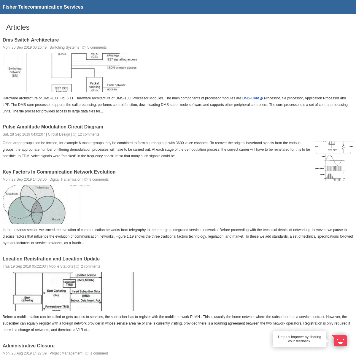
DMS SWITCH ARCHITECTURE Mon, 30 Sep 2019 00:26:49 | Switching Systems |5 comments
Hardware architecture of DMS-100. Fig. 6.11. Hardware architecture of DMS-100. Processor Modules. The main components of processor modules are DMS-Core Processor, file processor, Application Processor and LPP. The DMS-core processor supports the call processing, performs control function, down loading DMS super-node software and supports other peripheral controllers. The core processors is a set of central processing units. The file processor provides access to large data files for... PULSE AMPLITUDE MODULATION CIRCUIT DIAGRAM Sat, 28 Sep 2019 04:02:07 | Circuit Design | 12 comments Other larger groups can be formed, for example 6 mastergroups may be combined to form a jumbogroup with 3600 voice channels. To recover the original baseband signals from the various groups, the appropriate number of filtering demodulation processes will have to be carried out. At each stage of the demodulation process, the correct carrier will have to be reinstated for this to be possible. In FDM, voice signals were ''stacked'' in the frequency spectrum so that many suchsignals could be...
KEY FACTORS IN COMMUNICATION NETWORK EVOLUTION Mon, 23 Sep 2019 14:03:00 | Digital Transmission | 9 comments In the previous section we traced the evolution of communication networks from telegraphy to the emerging integrated services networks. Before proceeding with the technical details of networking, however, we pause to discuss factors that influence the evolution of communication networks. Figure 1.19 shows the three traditional factors technology, regulation, and market. To these we add standards, a set of technical specifications followed by manufacturers or service providers, as a fourth... LOCATION REGISTRATION AND LOCATION UPDATE Thu, 19 Sep 2019 05:22:03 | Mobile Stations | 2comments
Before a mobile station can be called or gets access to services, the subscriber has to register with the mobile network PLMN . This is usually the home network where the subscriber has a service contract. However, the subscriber can equally register with a foreign network provider in whose service area he or she is currently visiting, provided there is a roaming agreement between the two network operators. Registration is only required if there is a change of networks, and therefore a VLR of... ADMINISTRATIVE CLOSURE Mon, 26 Aug 2019 14:27:39 | Project Management | 1 comment Performance measurement documentation 2. Documentation of the product oi the project 1. Project archives 2 Formal acceptance Any loose ends are tied, and the project is essentially 'closed'. Although many team members are leaving the project, or maybe even have already left, the PM should get input from each of them on the lessons learned during the project, in order to help the next team to avoid the problems that this one faced. The intent is one of helping future projects - not tocast blame...
TERRESTRIAL MICROWAVE Mon, 15 Jul 2019 11:14:21 | Division Multiplexing| 3 comments
Microwaves do not follow the curvature of the earth and therefore require line-of-sight transmission and reception equipment. The distance coverable by a line-of-sight signal depends to a large extent on the height of the antenna the taller the antennas, the longer the sight distance. Height allows the signal to travel farther without being stopped by the curvature of the planet and raises the signal above many surface obstacles, such as low hills and tall buildings that would otherwise block... SOURCE CODING AND SPEECH PROCESSING Mon, 15 Jul 2019 11:14:21 | Mobile Stations | 2comments
Source coding reduces redundancy in the speech signal and thus results in signal compression, which means that a significantly lower bit rate is achieved than needed by the original speech signal. The speech coder decoder is the central part of the GSM speech processing function, both at the transmitter Figure 6.2 as well as at the receiver Figure 6.3 . The functions of the GSM speech coder and decoder are usually combined in one building block called the codec COder DECoder . Figure 6.2... SUBSCRIBER LOOP DESIGN Mon, 15 Jul 2019 11:14:21 | Switching Systems |3 comments
The cables that connect the telephone handsets or other devices to the local switching office or end office is referred as subscriber loop or local loop. Every suscriber has his own pair of wires to the local switching office. Twisted pair local loop is an excellent transmission medium for analog voicesignals. But it is
limited to low frequency audio signals. The introduction of fiber cable needs a device at subscriber premises to convert electrical energy into light energy and this is the... PLMN CONFIGURATIONS AND INTERFACES Mon, 15 Jul 2019 11:14:21 | Mobile Stations | 4comments
The fixed connections for transport of signaling and user data in aGSM PLMN Figure
3.8 are
standard transmission lines. Within the SMSS, lines with a transmission rate of 2 Mbit s or 1.544 Mbit s in North America are typically used fixed lines, mostly microwave links or leased lines . The BSS uses mostly 64 kbit s lines. Signaling has two fundamentally different parts GSM-specific signaling within the BSS, including the air interface, and signaling within the SMSS and with other PLMN in... TWO WIRE AND FOUR WIRE TRANSMISSION Mon, 15 Jul 2019 11:14:21 | Voice Channels A telephone conversation inherently requires transmission in both directions. When both directions are carried on the same pair of wires, it is called two-wire transmission. The telephones in our homes and offices are connected to a local switching center (exchange) by means of two-wire circuits. A more proper definition for transmitting and switching purposes is that when oppositely directed portions of a single telephone conversation occur over the same... PULSE AMPLITUDE MODULATION PAM Tue, 25 Jun 2019 04:48:45 | Division Multiplexing| 7 comments
The first step in analog-to-digital encoding is called pulse amplitude modulation PAM . This technique takes analog information, samples it, and generates a series of pulses based on the results of the sampling. The term sampling means measuring the amplitude of the signal at equal intervals. The method of sampling used in PAM is more useful to other areas of engineering than it is to data communication. However, PAM is the foundation of an important analog-to-digital encoding method called... REGENERATIVE REPEATERS Thu, 23 May 2019 09:37:57 | Voice Channels | 12comments
As we are probably aware, pulses passing down a digital transmission line suffer attenuation and are badly distorted by the frequency characteristic of the line. A regenerative repeater amplifies and reconstructs such a badly distorted digital signal and develops a nearly perfect replica of the original at its output. Regenerative repeaters are an essential key to digital transmission in that we could say that the noise stops at the repeater. Figure 6.11 is a simplified block diagram ofa...
DIGITAL SWITCHING SYSTEMS Wed, 08 May 2019 13:21:25 | Switching Systems |2 comments
Various facilities of digital switching and transmission is the reason why the analog switching is slowly getting replaced by digital switching. The incorporation of digital switching and transmission technique into telecommunications altered the whole telecommunication industries setup. The reliability of digital switching systemis becoming
increasingly important for users of telephone services. Voice and or data can be represented using digital signals efficiently than analogsignals. A...
MICROSTRIP DIRECTIONAL COUPLERS Thu, 11 Apr 2019 01:09:41 | Radio Engineering Let us consider two parallel microstrip lines that are placed so close to each other that the fields of the lines couple to each other. Then a wave propagating in one line can excite a wave in the other line. The fields of a coupled line can be presented as a superposition of an even mode and an odd mode, shown in Figure 6.9. In case of the even mode the currents of the lines are equal and in the same direction in case of the odd mode they are equal but in the opposite directions. Acoupled...
DEFINITION OF ECHO AND SINGING Sun, 17 Mar 2019 11:26:02 | Network Management | 1 comment As the name implies, echo in telephone systems is the return of a talker's voice. It is most apparent to the talker himself or herself. Secondarily, it can also be an annoyance to the listener. To be an impairment, the returned voice must suffer some noticeable delay. Thus we can say that echo is a reflection of the voice. The cause of echo is impedance mismatches that might be present any place in the electrical telephone connection. Echo is a major annoyance to thetelephone user....
CLASSIFICATION AND COMPARISON OF MAC PROTOCOLS Fri, 08 Feb 2019 19:32:52 | Sensor Networks In general, wireless communication has a variety of MAC protocols, which can be classified into distinct groups according to different criteria. Based on whether a central controller is involved in coordination, WSNs' MAC protocols can be categorized as centralized, distributed (decentralized), and hybrid. Actually, hybrid protocols attempt to combine the advantages of centralized and distributed schemes, but can be more complex. Figure 18.3 shows such classification 97 . Centralized MAC... THE STROWGER STEP BY STEP SWITCHING SYSTEM Tue, 29 Jan 2019 11:34:03 | Switching Systems |4 comments
Several electromechanical switching system were developed around 1880-1890 to eliminate the limitations of manual exchanges and to establish automatic exchanges to improve the speed and carry more leads subscribers . Among those electromechanical automatic switches, strowger's step by step switching system was the most pupular and widely used and even now in some part of the world, it is in use. The history of this switching system is described briefly in the following paragraph. The first... TELESERVICES AND BEARER SERVICES Mon, 01 Oct 2018 16:36:49 | Service Providers | 2 comments Teleservices are defined at the user interfaces but the bearer services at the network interfaces of the terminal equipment as can be seen in figure 5.3.1. teleservices are telecommunication services which provide full communication in between users according to the agreed protocol of network operators including the terminal equipment functions bearer services are telecommunication services providing the signal transmission capabilities in between network access points Fig 5.3.1Definitions of...
ADVANTAGES AND DISADVANTAGES OF A LOW EARTH ORBIT Sun, 23 Sep 2018 14:55:08 | Network Management | 1 comment The low earth orbit (LEO) offers a number of advantages over the geostationary orbit, and at least one serious disadvantage. Delay. One-way delay to a GEO satellite is budgeted at 125 ms one-way up and down is double this value of 250 ms. Round-trip delay is about 0.5 s. Delay to a typical LEO is 2.67 ms and round-trip delay is 4 x 2.67 ms or about 10.66 ms. Calls to from mobile users of such systems may be relayed still again by conventional satellite services. Data services do not have to be... OMA POC TALK BURST CONTROL Fri, 01 Jun 2018 15:46:29 | Multimedia Telephony | 1 comment PoC is a half-duplex, one-way communication method between participants and implies that one party speaks while the other parties listen this requires a talk burst control mechanism, also known as floor control. The talk burst control mechanism in OMA PoC is a confirmed request grant procedure within the PoC server performing the controlling PoC function, insuring that only one user is sending media at a given time. The talk burst control mechanism in OMA PoC forms a second control layerunder...
QUADRATURE DETECTOR CIRCUIT Fri, 18 May 2018 05:16:41 | Circuit Design Figure 5.4. a The phasor diagram when signal frequency is lower than carrier frequency. b The phasor diagram when signal frequency is higher than carrier frequency. Figure 5.4. a The phasor diagram when signal frequency is lower than carrier frequency. b The phasor diagram when signal frequency is higher than carrier frequency. Replacing R2 in Equation 5.2.7 by Z2 gives It is evident that V1 and V2 are no longer at right angles to each other. The angle between them depends on the magnitude and... EXTENDING THE SUBSCRIBER LOOP Thu, 21 Sep 2017 10:05:49 | Voice Channels In many situations, subscribers will reside outside of the maximumsubscriber loop
lengths described above. There are five generally accepted methods that can be used to extend these maximums. They are 1. Increase conductor diameter (covered above). 2. Use amplifiers and or range extenders.6 4. Use digital subscriber line (DSL) techniques (covered in Chapter 6). 5. Employ remote concentrators or switches (see Section 4.3). Amplifiers in the subscriber loopextend the
transmission range. Perhaps... CONTINUOUS VARIABLE SLOPE DELTA MODULATION Thu, 31 Aug 2017 14:09:31 | Bluetooth Technology | 5 comments Continuous Variable Slope Delta Modulation was first proposed by Greefkes and Riemes in 1970. CVSD requires a 1-bit sample length compared to the 8 bits used in PCM, so more samples can be sent in the same bandwidth. As a result, CVSD is more tolerant of communications errors. Because of its error tolerance, CVSD performs well in noisy channels, and for this reason, it has been widely used in military communications systems.The ability to tolerate errors is also what makes CVSD attractive for... PHASE DIVISION MULTIPLEXING Mon, 08 May 2017 18:05:10 | Division Multiplexing| 7 comments
The term phase describes the position of the waveform relative to time zero. If we think of the wave as something that can be shifted backward or forward along the time axis, phase describes the amount of that shift. It indicates the status of the first cycle. Phase is measured in degrees or radians 360 degrees is 2n radians . A phase shift of 360 degrees corresponds to a shift of a complete period a phase shift of 180 degrees corresponds to a shift of half a period and a phase shift of 90... BUILDING PENETRATION LOSS MODELS Thu, 23 Feb 2017 22:54:02 | Radio Wave The building penetration lossis defined
as the power loss that an electromagnetic wave undergoes as it propagates from outside a building towards one or several places inside this building. This parameter is determined from the comparison between the external field and the field present in different parts of the building where the receiver is located. Penetration loss models, being integrated into the coverage prediction tools, must take into account the environment around the buildings which... REFLECTION AND TRANSMISSION AT A DIELECTRIC INTERFACE Tue, 15 Nov 2016 05:58:00 | Radio Engineering Let us consider a plane wave that is incident at a planar interface of two lossless media, as illustrated in Figure 2.7. The wave comes from medium 1, which is characterized by 1 and 1, to medium 2 with 2 and 2. The planar interface is at z 0. The angle of incidence is d1 and the propagation vector k 1 is in the xz-plane. Part E from the incident field is reflected at an angle d and part E2 is transmitted through the interface and leaves at an angle of 62. Figure 2.7 Reflection andtransmission...
GSM NETWORK CONNECTION TO SS7 NETWORKS Mon, 27 Feb 2017 06:59:12 | Broadband The MSC is the Central Switching function of the GSM network. The MSC is
connected to a SS7 network for the purpose of signaling and performing database queries. The SS7 network uses a network node called the STP, which is a packet switching node (can be SS7, IP, or X.25). Using a 64 Kbps channel connection between STPs, the network can process its signaling information. Next in a SS7 network is the use of the SCP, which houses the databases congruent to the network. In many casesthese...
CONCLUSION AND FUTURE WORK Tue, 22 Nov 2016 14:43:18 | Wireless Networks Through a series of experiments and measurements made at various locations of the AUT's WY office building, we gained an insight into the performance of Wi-Fi links in an office environment. This project involves both literature review and practical investigation regarding the IEEE 802.11b protocol known as Wi-Fi. A number of conclusions can be drawn from the findings of this study. The use of electromagnetic waves as the medium instead of cables presents many technical challenges. To begin... About | Contact | Write For Us | Shop | Privacy Policy| Resources
Feedback
Help us improve by sharing your feedback. Thank you for sharing yourfeedback with us!
How would you rate your experience?Hate
Dislike
Neutral
Like
Love
Select an element on the page. Enter your email address if you would like to receive a follow up. Thank you for sharing your feedback with us! Connecting your feedback with data related to your visits (device-specific, usage data, cookies, behavior and interactions) will help us improve faster. Do you give us your consent to do so for your previous and future visits? More information__ __
Not using Hotjar
yet?
Skip Send
Select an element on the page.Details
4