2
More Annotations


1


4
Favourite Annotations


6


2
Text
LEARNING INSTRUMENTATION AND CONTROL ENGINEERINGINSTRUMMENT ENGINEERSPRESSURE SWITCHPNEUMATIC SYSTEMSPRESSURE GAUGESCALIBRATION The most common control valve actuator used in the industry is the diaphragm actuator. Diaphragm actuators, as in the case of valve bodies, can be classified as either direct or reverse acting. FLOW INSTRUMENTATION: PRINCIPLES AND FORMULAS ~ LEARNING The measurement of fluid flow is arguably the single most complex type of process variable measurement in all of industrial instrumentation. This is because there are vast array of flow metering technologies that can be used to measure fluid flow each one with its PIPING AND INSTRUMENTATION DIAGRAMS TUTORIALS III: FLOW A Tutorial on How to Develop a Piping and Instrumentation Diagram (P&ID) To develop the P&ID from the information given above, you need to be familiar with most of the symbols used for representing flow and level since we are basically dealing with only flow and level control
here.
INSTRUMENTATION BASICS: 4 The most popular form of signal transmission used in modern industrial instrumentation systems is the 4-20 mA DC standard. This is an analog signal standard, meaning that the electric current is used to proportionately represent measurements or control signals. PNEUMATIC INSTRUMENTATION PRINCIPLES Practically all pneumatic measuring systems depend on a primary element such as an orifice plate, Bourdon tube, etc., to convert the physical parameter to be measured into either a force or a displacement which, in turn, can be sensed by some form of flapper/nozzle sensor or used directly to operate a mechanism such as an indicator, a recorder pen, or a switch. DP TRANSMITTER VALVE MANIFOLDS ~ LEARNING INSTRUMENTATION An important accessory to the DP transmitter is the valve manifold. Most DP transmitters come with either a 3-valve manifold or a 5-valve manifold or a single HOW TO SPECIFY A THERMOWELL ~ LEARNING INSTRUMENTATION AND Thermowells are available for light duty applications, high pressures, high temperatures and high velocity applications. They are used to meet many general service industry needs and are selected on the basis of pressure, temperature, flow, vibration and corrosion parameters. HOW TO CALIBRATE YOUR DP TRANSMITTER ~ LEARNING You are now ready to calibrate the DP transmitter. Note that during the calibration process, the transmitter’s zero percent, (LRV), is to be calibrated to the , LRV, of the calibration range and the transmitter’s span is to be calibrated to the, URV, of the calibration range.For example, suppose a DP transmitter with output 4 – 20mA is to be used to measure pressure in the range 0 BASICS OF PERMANENT PRESSURE LOSS IN DIFFERENTIAL PRESSURE The standard primary flow sensors commonly used in differential pressure flow meters are the orifice plates, flow nozzles and venturi tubes. These flow meters are often called "head loss" meters because there is a permanent pressure loss downstream these meters. BUBBLER TUBE SYSTEM FOR LEVEL MEASUREMENT Bubbler tubes provide a simple and inexpensive but less accurate (±1-2%) level measurement system for corrosive or slurry-type applications or in open or vented containers, especially those in harsh environments such as cooling tower sumps, swimming pools, reservoirs, vented fuel tanks, drain sumps, air LEARNING INSTRUMENTATION AND CONTROL ENGINEERINGINSTRUMMENT ENGINEERSPRESSURE SWITCHPNEUMATIC SYSTEMSPRESSURE GAUGESCALIBRATION The most common control valve actuator used in the industry is the diaphragm actuator. Diaphragm actuators, as in the case of valve bodies, can be classified as either direct or reverse acting. FLOW INSTRUMENTATION: PRINCIPLES AND FORMULAS ~ LEARNING The measurement of fluid flow is arguably the single most complex type of process variable measurement in all of industrial instrumentation. This is because there are vast array of flow metering technologies that can be used to measure fluid flow each one with its PIPING AND INSTRUMENTATION DIAGRAMS TUTORIALS III: FLOW A Tutorial on How to Develop a Piping and Instrumentation Diagram (P&ID) To develop the P&ID from the information given above, you need to be familiar with most of the symbols used for representing flow and level since we are basically dealing with only flow and level controlhere.
INSTRUMENTATION BASICS: 4 The most popular form of signal transmission used in modern industrial instrumentation systems is the 4-20 mA DC standard. This is an analog signal standard, meaning that the electric current is used to proportionately represent measurements or control signals. PNEUMATIC INSTRUMENTATION PRINCIPLES Practically all pneumatic measuring systems depend on a primary element such as an orifice plate, Bourdon tube, etc., to convert the physical parameter to be measured into either a force or a displacement which, in turn, can be sensed by some form of flapper/nozzle sensor or used directly to operate a mechanism such as an indicator, a recorder pen, or a switch. DP TRANSMITTER VALVE MANIFOLDS ~ LEARNING INSTRUMENTATION An important accessory to the DP transmitter is the valve manifold. Most DP transmitters come with either a 3-valve manifold or a 5-valve manifold or a single HOW TO SPECIFY A THERMOWELL ~ LEARNING INSTRUMENTATION AND Thermowells are available for light duty applications, high pressures, high temperatures and high velocity applications. They are used to meet many general service industry needs and are selected on the basis of pressure, temperature, flow, vibration and corrosion parameters. HOW TO CALIBRATE YOUR DP TRANSMITTER ~ LEARNING You are now ready to calibrate the DP transmitter. Note that during the calibration process, the transmitter’s zero percent, (LRV), is to be calibrated to the , LRV, of the calibration range and the transmitter’s span is to be calibrated to the, URV, of the calibration range.For example, suppose a DP transmitter with output 4 – 20mA is to be used to measure pressure in the range 0 BASICS OF PERMANENT PRESSURE LOSS IN DIFFERENTIAL PRESSURE The standard primary flow sensors commonly used in differential pressure flow meters are the orifice plates, flow nozzles and venturi tubes. These flow meters are often called "head loss" meters because there is a permanent pressure loss downstream these meters. BUBBLER TUBE SYSTEM FOR LEVEL MEASUREMENT Bubbler tubes provide a simple and inexpensive but less accurate (±1-2%) level measurement system for corrosive or slurry-type applications or in open or vented containers, especially those in harsh environments such as cooling tower sumps, swimming pools, reservoirs, vented fuel tanks, drain sumps, air BASICS OF RESISTANCE TEMPERATURE DETECTORS (RTDS The alpha value is the temperature coefficient for that specific material and composition. Copper elements have a different alpha value than platinum elements, and platinum elements themselves can vary depending on the purity of the platinum and any alloy content. INSTRUMENT ABBREVIATIONS USED IN INSTRUMENTATION DIAGRAMS The table below contains some of the instrument abbreviations used in conjunction with P&ID symbols in instrumentation diagrams. I have dealt with some of them before but for the purpose of emphasis and completeness let us go through again.BASICS OF THE 4
The 4-20mA current loop is a very robust and popular sensor signalling standard. Current loops are ideal for data transmission because of their inherent insensitivity to electrical noise. INSTRUMENT ABBREVIATIONS USED IN INSTRUMENTATION DIAGRAMS The main objective of bringing many possible combinations of these process instruments is to drive home the understanding of how they are formed such that once you see them being used in a process or instrumentation diagram or even conceptual or flow diagrams, you will immediately be in a position to identify them and know what they arebeing used for.
HOW TO SPECIFY A THERMOWELL ~ LEARNING INSTRUMENTATION AND Thermowells are available for light duty applications, high pressures, high temperatures and high velocity applications. They are used to meet many general service industry needs and are selected on the basis of pressure, temperature, flow, vibration and corrosion parameters. INTRINSIC SAFETY AND SAFETY BARRIERS ~ LEARNING Intrinsic safety (IS) is a method of providing safe operation of electronic process‐control instrumentation in hazardous areas. IS systems keep the available electrical energy in the system low enough that ignition of the hazardous atmosphere cannot occur. HOW TO CALIBRATE AND ADJUST A PRESSURE SWITCH ~ LEARNING How to calibrate and adjust a pressure switch. Dead-band or Reset: This is a setting that determines the amount of pressure change required to re-set the switch to its normal state after it hastripped.
BUBBLER TUBE SYSTEM FOR LEVEL MEASUREMENT Bubbler tubes provide a simple and inexpensive but less accurate (±1-2%) level measurement system for corrosive or slurry-type applications or in open or vented containers, especially those in harsh environments such as cooling tower sumps, swimming pools, reservoirs, vented fuel tanks, drain sumps, air FLOW METERS ACCURACY AND TERMINOLOGY ~ LEARNING Flow meters are very popular devices that help to determine the quantity of fluids through pipes at any given time. The majority of flow meters are applied in custody transfer applications where a seller of a given fluid –gasoline, natural gas etc needs to make sure that the actual quantity of fluid is being sold to a buyer and of course the buyer needs to ensure that he is getting value for COMMON RTD APPLICATION PROBLEMS AND THEIR REMEDIES This is the resistance to current leakage through and over the surface of the insulation material of the sensor wires. A high insulation resistance implies a sensor in good condition while a low insulation resistance implies some problems with the RTD sensor which could result in current leakage. PIPING AND INSTRUMENTATION DIAGRAMS TUTORIALS III: FLOW A Tutorial on How to Develop a Piping and Instrumentation Diagram (P&ID) To develop the P&ID from the information given above, you need to be familiar with most of the symbols used for representing flow and level since we are basically dealing with only flow and level controlhere.
HOW A THERMOSTAT WORKS ~ LEARNING INSTRUMENTATION AND The schematic of a simple rod thermostat is shown above. The thermostat comprises two elements – Brass and Invar - that expand atdifferent rates.
FLOW INSTRUMENTATION: PRINCIPLES AND FORMULAS ~ LEARNING The measurement of fluid flow is arguably the single most complex type of process variable measurement in all of industrial instrumentation. This is because there are vast array of flow metering technologies that can be used to measure fluid flow each one with itsBASICS OF THE 4
The 4-20mA current loop is a very robust and popular sensor signalling standard. Current loops are ideal for data transmission because of their inherent insensitivity to electrical noise. INTRINSIC SAFETY AND SAFETY BARRIERS ~ LEARNING Intrinsic safety (IS) is a method of providing safe operation of electronic process‐control instrumentation in hazardous areas. IS systems keep the available electrical energy in the system low enough that ignition of the hazardous atmosphere cannot occur. BUBBLER TUBE SYSTEM FOR LEVEL MEASUREMENT Bubbler tubes provide a simple and inexpensive but less accurate (±1-2%) level measurement system for corrosive or slurry-type applications or in open or vented containers, especially those in harsh environments such as cooling tower sumps, swimming pools, reservoirs, vented fuel tanks, drain sumps, air OPERATING PRINCIPLE OF NUCLEAR LEVEL SENSORS ~ LEARNING Nuclear based level measurement sensors can be used for point as well as continuous level measurement applications. The concept of nuclear level sensors is based on the fact that certain types of nuclear radiation easily penetrate the walls of industrial vessels, but is attenuated by traveling through the bulk of material stored withinthose vessels.
HOW TO USE A THERMOCOUPLE: PRACTICAL APPLICATION TIPS Well a detailed study of the thermocouple will reveal that it is not really a simple device as it seems. From the extension cables that could serve as antenna to pick up stray voltages, to ground loop problems, to advanced signal conditioning modules applied to curb noise and composition challenges in the thermocouple material, it does not appear to be a simple device in the real sense. HOW TO ZERO A PRESSURE TRANSMITTER Pressure Transmitter, Transmitter zero, Zeroing Pressure Transmitter. Zeroing a transmitter involves bringing the transmitter to zero signal but does not remove the transmitter from service.The most popular transmitter manifolds are either a 3 or 5-Valve manifold and the operations involved in zeroing a transmitter using these manifolds aredifferent.
BASICS OF PERMANENT PRESSURE LOSS IN DIFFERENTIAL PRESSURE The standard primary flow sensors commonly used in differential pressure flow meters are the orifice plates, flow nozzles and venturi tubes. These flow meters are often called "head loss" meters because there is a permanent pressure loss downstream these meters. PIPING AND INSTRUMENTATION DIAGRAMS TUTORIALS III: FLOW A Tutorial on How to Develop a Piping and Instrumentation Diagram (P&ID) To develop the P&ID from the information given above, you need to be familiar with most of the symbols used for representing flow and level since we are basically dealing with only flow and level controlhere.
FLOW INSTRUMENTATION: PRINCIPLES AND FORMULAS ~ LEARNING The measurement of fluid flow is arguably the single most complex type of process variable measurement in all of industrial instrumentation. This is because there are vast array of flow metering technologies that can be used to measure fluid flow each one with its BASICS OF THE HART COMMUNICATION PROTOCOL -WORKING The worldwide accepted standard for analog signals in the measurement industry is the 4 to 20mA signal. One key drawback of this signalstandard is that it
DIGITAL COMMUNICATION MODES & NETWORK CONFIGURATIONS IN The HART Communication Protocol enables several instruments to be connected on the same pair of wires in a multi-drop network configuration. The current through each field device is fixed at a minimum value (typically 4mA) sufficient for device operation. OPERATING PRINCIPLE OF VARIABLE AREA FLOW METERS The variable area flowmeter is a reverse differential pressure meter used to accurately measure the flow rate of liquids and gases. The flow meter generally comprises a vertical, tapered glass tube and a weighted float whose diameter is approximately the same as the tubebase.
HOW TO SPECIFY A THERMOWELL ~ LEARNING INSTRUMENTATION AND Thermowells are available for light duty applications, high pressures, high temperatures and high velocity applications. They are used to meet many general service industry needs and are selected on the basis of pressure, temperature, flow, vibration and corrosion parameters. HOW TO CALIBRATE YOUR DP TRANSMITTER ~ LEARNING You are now ready to calibrate the DP transmitter. Note that during the calibration process, the transmitter’s zero percent, (LRV), is to be calibrated to the , LRV, of the calibration range and the transmitter’s span is to be calibrated to the, URV, of the calibration range.For example, suppose a DP transmitter with output 4 – 20mA is to be used to measure pressure in the range 0 BASICS OF PERMANENT PRESSURE LOSS IN DIFFERENTIAL PRESSURE The standard primary flow sensors commonly used in differential pressure flow meters are the orifice plates, flow nozzles and venturi tubes. These flow meters are often called "head loss" meters because there is a permanent pressure loss downstream these meters. HOW TO ZERO A PRESSURE TRANSMITTER Pressure Transmitter, Transmitter zero, Zeroing Pressure Transmitter. Zeroing a transmitter involves bringing the transmitter to zero signal but does not remove the transmitter from service.The most popular transmitter manifolds are either a 3 or 5-Valve manifold and the operations involved in zeroing a transmitter using these manifolds aredifferent.
HOW TO CONVERT RESISTANCE TO TEMPERATURE ~ LEARNING Where: R(T2) = Resistance at temperature T2 R(T1) = Resistance at temperature T1 α = Temperature coefficient of resistance ΔT = (T2 – T1), Temperature difference between T1 and T2 The principle of temperature change with resistance is what is utilized in Resistance Temperature Detectors, RTDs to sense and measure temperature in many industrial applications. Learning Instrumentation And Control Engineering Learning Instrumentation And Control Engineering LEARNING INSTRUMENTATION AND CONTROL ENGINEERING We Provide Tools and Basic Information for Learning Process Instrumentation and Control Engineering. CONTROL VALVE ACTUATORS FAILURE MODESCustom Search
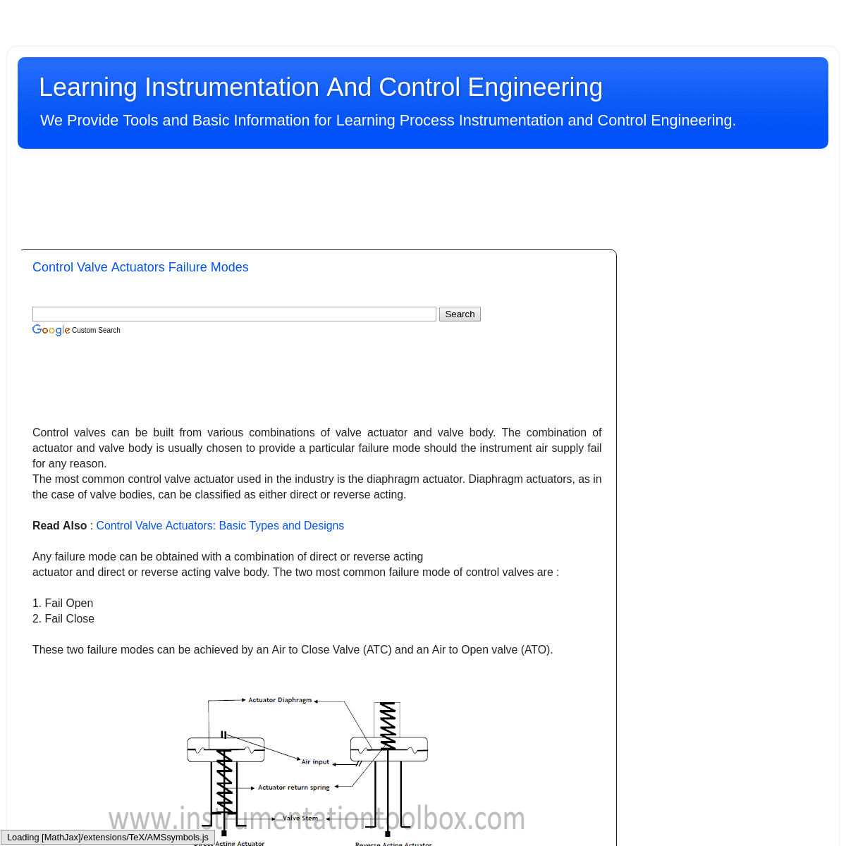
Control valves can be built from various combinations of valve actuator and valve body. The combination of actuator and valve body is usually chosen to provide a particular failure mode should the instrument air supply fail for any reason. The most common control valve actuator used in the industry is the diaphragm actuator. Diaphragm actuators, as in the case of valve bodies, can be classified as either direct or reverse acting. READ ALSO : Control Valve Actuators: Basic Types and Designs Any failure mode can be obtained with a combination of direct orreverse acting
actuator and direct or reverse acting valve body. The two most common failure mode of control valves are :1. Fail Open
2. Fail Close
These two failure modes can be achieved by an Air to Close Valve (ATC) and an Air to Open valve (ATO). AIR TO CLOSE CONTROL VALVE (ATC) An air to close (ATC) valve and therefore fail open valve, can be obtained with the combination of a reverse acting actuator and a reverse acting valve body or a direct acting actuator and a directacting valve body.
AIR TO OPEN CONTROL VALVE (ATO) An air to open (ATO) valve and therefore fail close valve, can be obtained with a combination of direct actuator and reverse body or reverse actuator and direct Body. VALVE BODY AND ACTUATOR COMBINATION AND THEIR FAILURE MODES The action of an actuator can easily be determined (usually by whether the air is supplied to the upper or lower half of the housing). Direct or reverse acting valve bodies are not always readily identifiable. Most often, reference to the nameplate or flow sheet is usually necessary to correctly identify the action of a valve body – reverse acting or direct acting. Listed in the table below are all possible combinations of valve body and actuator and their failure modes:VALVE ACTUATOR
VALVE BODY
VALVE ACTION
FAILURE MODE
Direct
Direct
Air to Close
Fail Open
Reverse
Reverse
Air to Close
Fail Open
Direct
Reverse
Air to Open
Fail Closed
Reverse
Direct
Air to Open
Fail Closed
Links to this post
Email This
BlogThis!
Share to Twitter
Share to Facebook
Labels: Control Valves BASICS OF SPLIT-RANGE CONTROL IN CONTROL VALVE APPLICATIONSCustom Search
In many process control applications in industry, it is sometimes desirable to have multiple control valves respond to the output of a single common controller. CONTROL VALVES CONFIGURED IN THIS WAY TO FOLLOW THE COMMAND OF A SINGLE CONTROLLER ARE SAID TO BE SPLIT-RANGED,OR SEQUENCED.
Split-ranged control valves may assume different forms of sequencing. Common modes of control valve sequencing seen in the process industry are: complementary, exclusive, and progressive. COMPLEMENTARY SPLIT-RANGE CONTROL With this form of split-ranging, there is never a condition in the controller’s output range where both valves are fully open or fully shut. Rather, each valve complements the other’s position. A typical example of complementary split-range control is a situation where two valves serve to proportion a mixture of two fluid streams, such as where base and pigment liquids are mixed together to form colored paint as shown below: Example of complementary split-range control. Both base and pigment valves operate from the same controller output signal. While the pigment valve is Air-To-Open, the base valve is Air-To-Close. The following table shows the relationship between valve opening for each control valve and the controller’s output: CONTROLLER OUTPUT (%)I/P OUTPUT (PSI)
PIGMENT VALVE (STEM POSITION) BASE VALVE (STEM POSITION)0
3
Fully Closed
Fully Open
25
6
25% Open
75% Open
50
9
Half-Open
Half - Open
75
12
75% Open
25% Open
100
15
Fully Open
Fully Closed
EXCLUSIVE SPLIT-RANGE CONTROL The nature of valve sequencing in this type of split-range control is to have an “EITHER OR” throttled path for process fluid. That is, either process fluid flows through one valve or through the other, but never through both at the same time. This type of split-ranged control valves call for a form of valve sequencing where both valves are fully closed at a 50% controller output signal, with one valve opening fully as the controller output drives toward 100% and the other valve opening fully as the controlleroutput goes to 0%.
A practical example of this form of split-ranging is in reagent feed to a pH neutralization process, where the pH value of process liquid is brought closer to neutral by the addition of either acid orcaustic:
Exclusive Split-Range Control The basic operating principle of the above process is: * A pH analyzer monitors the pH value of the mixture and a single pH controller commands two reagent valves to open whenneeded.
* If the process pH begins to increase, the controller output signal increases as well (direct action) to open up the acidvalve.
* The addition of acid to the mixture will have the effect of lowering the mixture’s pH value. * Conversely, if the process pH begins to decrease, the controller output signal will decrease as well, closing the acid valve and opening the caustic valve. * The addition of caustic to the mixture will have the effect of raising the mixture’s pH value. The Air-To-Open acid valve has an operating range of 9 to 15 PSI, while the Air-To-Close caustic valve has an operating of 9 to 3 PSI. The table below shows the relationship between valve opening for each control valve and the controller’s output: CONTROLLER OUTPUT (%)I/P OUTPUT (PSI)
ACID VALVE (STEM POSITION) CAUSTIC VALVE (STEM POSITION)0
3
Fully Closed
Fully Open
25
6
Fully Closed
Half - Open
50
9
Fully Closed
Fully Closed
75
12
Half - Open
Fully Closed
100
15
Fully Open
Fully Closed
PROGRESSIVE SPLIT-RANGE CONTROL This form of split-range control for control valves is used to expand the operating range of flow control for some fluid beyond that which a single control valve could deliver. In this type of control, one of the valve usually a small valve opens gradually and becomes fully open at 50% of controller output while the large valve will remain shut at until the controller output goes beyond 50% when it starts opening. Both valves become fully open when controller output is 100%. An example of progressive split-range control is a pH control process where the incoming liquid always has a high pH value, and must be neutralized with acid as shown below: An example of progressive split-range control The PH of the incoming water to be treated is measured by the analyzer, AT. As the output of controller AIC increases, the small acid valve starts to open and becomes fully open at 50% of controller output. Meanwhile the large acid valve will remain shut until controller output goes beyond 50%. At 100%, both small and large acid valves are fully open to ensure that the PH of the incoming water isneutralized.
Controller output and valve status for proper sequencing of the small and large acid control valves is shown below: CONTROLLER OUTPUT (%)I/P OUTPUT (PSI)
SMALL ACID VALVE (STEM POSITION) LARGE ACID VALVE (STEM POSITION)0
3
Fully Closed
Fully Closed
25
6
Half Open
Fully Closed
50
9
Fully Open
Fully Closed
75
12
Fully Open
Half Open
100
15
Fully Open
Fully Open
Links to this post
Email This
BlogThis!
Share to Twitter
Share to Facebook
Labels: Control Valves, Process Control
HOW A SELF OPERATED PRESSURE REDUCING REGULATOR WORKSCustom Search
A self operated pressure reducing regulator is a mechanical device that is used to control and reduce pressure especially in natural gas plants. A pressure regulator is essentially a force balanced device that adjusts to changes in the system it is controlling. There are two types of pressure reducing regulators used in natural gas systems: 1. Self operated regulators 2. Pilot operated regulators Both types of regulators are very common in the gas industry the self-operated regulators are general used in lower flow and lower pressure system, and are less expensive regulators. While the pilot operated regulators are generally use in higher flow situation, like city gates, large customers, industrial accounts etc and where you have higher pressure to control. BASIC PARTS OF A SELF OPERATED PRESSURE REDUCING REGULATORS Self Operated regulators consist of three basic components: 1. A loading element. 2. A measuring element and 3. A restrictive element as shown below Self Operated Pressure Reducing Regulator As seen above, the loading element is typically a spring but it can also be a weight or pressure from some external source. When the spring is compressed, it exerts a loading force. The measuring element or diaphragm is connected to the process fluid (gas) that is being controlled and creates a force opposing the loading force. The restricting element or valve is connected to the spring and diaphragm assembly and regulates the flow through the regulator. OPERATING PRINCIPLE OF SELF OPERATED PRESSURE REDUCING REGULATORS In a self operated pressure regulator, as downstream system pressure decreases the spring force overcomes the force of the gas acting on the effective area of the diaphragm and the valve opens increasing flow into the system. When system pressure increases, the measuring force (the force of the system gas acting on the effective area of the diaphragm) overcomes the loading force (spring force) and closes the valve reducing flow into the system.Links to this post
Email This
BlogThis!
Share to Twitter
Share to Facebook
Labels: pressure sensors WHAT IS DAMPING IN PROCESS TRANSMITTERSCustom Search
A process transmitter typically ”measures” a process variable – flow, level, temperature, pressure - and produces an output in response to changes in the input variable. Most transmitters incorporates a sensor which measures the input variable and gives out an output of which 4 – 20m A is common. Of critical importance in the performance of a transmitter is a concept called damping. As the input variable changes, the transmitter output must update and change accordingly. Damping is the amount of time required, in addition to the update time, for the output of the transmitter to reach 63.2% of its final value after a step change has been applied to the input. A typical damping response curve of a process transmitter is shown below: Transmitter damping is adjustable from 1 to 32 seconds. Damping reduces the effects of electrical noise and any other insignificant transient noise that may influence the transmitter output signal. It is often used to stabilize control loops and prevent false trips. In the absence of electrical or transient noise, damping may not be required in processes that are slow and have inherent lag time e.g temperature control loops. Damping should be minimized in fast changing process conditions.Links to this post
Email This
BlogThis!
Share to Twitter
Share to Facebook
Labels: Transmitters ANSI B16.5 - MAXIMUM PRESSURE AND TEMPERATURE RATINGS OF FLANGES ANDFLANGE FITTINGS
Custom Search
The Maximum allowable non-shock pressure (psig) and temperature ratings for steel pipe flanges and flanged fittings according the American National Standard ANSI B16.5 are given in the table below. Flanges and their Fittings are a common feature in the process plants. The need to accurately determine their pressure rating and corresponding temperature ratings is important for personnel and plant safety and overall plant performance and reliability: MAXIMUM ALLOWABLE NON-SHOCK PRESSURE (PSIG)TEMPERATURE (°F)
PRESSURE CLASS (LB)
150
300
400
600
900
1500
2500
HYDROSTATIC TEST PRESSURE (PSIG)450
1125
1500
2225
3350
5575
9275
-20 TO 100
285
740
990
1480
2220
3705
6170
200
260
675
900
1350
2025
3375
5625
300
230
655
875
1315
1970
3280
5470
400
200
635
845
1270
1900
3170
5280
500
170
600
800
1200
1795
2995
4990
600
140
550
730
1095
1640
2735
4560
650
125
535
715
1075
1610
2685
4475
700
110
535
710
1065
1600
2665
4440
750
95
505
670
1010
1510
2520
4200
800
80
410
550
825
1235
2060
3430
850
65
270
355
535
805
1340
2230
900
50
170
230
345
515
860
1430
950
35
105
140
205
310
515
860
1000
20
50
70
105
155
260
430
Details
6