3
More Annotations


5


3
Favourite Annotations


1


6
Text
CIRCUIT DIAGRAM
Circuit Diagram is a free application for making electronic circuit diagrams and exporting them as images. Design circuits online in your browser or using the desktop application. CIRCUIT DIAGRAM WEB EDITOR Create electronic circuit diagrams online in your browser with the Circuit Diagram Web Editor. DOWNLOAD - CIRCUIT DIAGRAM Download the latest version of Circuit Diagram, a free, open-source program for making electronic circuit diagrams. WEB EDITOR GETTING STARTED Editing. Ctrl + Z: undo. Ctrl + Y: redo. Ctrl + C: copy the selected components or layers to the clipboard. Ctrl + X: cut the selected components or layers to the clipboard. Ctrl + V: paste components or layers from the clipboard. Delete: delete the selected components or layers. Ctrl + G: combine the selected components into a layer group. CIRCUIT DIAGRAM DOCUMENTNEW COMPONENTS
3. Create an issue requesting the new component. Create an issue on the components project requesting the new component. If possible, try to include an image of what it should look like. 4. Create it yourself. The quickest way is to create the component yourself. You can learn how to do this by following the Components docs.BASIC EXAMPLE
Option 1: VS Code Extension. If you are using the VS Code extension, click the Circuit Diagram icon in the top right corner above the file. This will render the component and open the image in a pane to theright.
LOCAL SETUP
The Circuit Diagram CLI is a utility that can compile components and render them as images. Download the appropriate version for your platform from the Circuit Diagram downloads page. Extract the downloaded file. For Linux, follow the additional installation steps. 2. Install Visual Studio Code. FLAGS - DOCS - CIRCUIT DIAGRAM Flags are placed in the tag of the component file, and allow you to set special options when conditions are met.. Flags can be used to control the layout of a component. < flags conditions = " CONDITIONS " > < option > FLAG_NAME < option > FLAG_NAME The following flag options are available: HorizontalOnly. Only allows the component to be placedWEB EDITOR FAQ
Can I create a copy of an existing saved circuit? Use the following workaround to create a copy of an existing saved circuit: 1. Download the circuit as a CDDX Circuit. 2. Click Open, then Import and select the file downloaded in step 1.CIRCUIT DIAGRAM
Circuit Diagram is a free application for making electronic circuit diagrams and exporting them as images. Design circuits online in your browser or using the desktop application. CIRCUIT DIAGRAM WEB EDITOR Create electronic circuit diagrams online in your browser with the Circuit Diagram Web Editor. DOWNLOAD - CIRCUIT DIAGRAM Download the latest version of Circuit Diagram, a free, open-source program for making electronic circuit diagrams. WEB EDITOR GETTING STARTED Editing. Ctrl + Z: undo. Ctrl + Y: redo. Ctrl + C: copy the selected components or layers to the clipboard. Ctrl + X: cut the selected components or layers to the clipboard. Ctrl + V: paste components or layers from the clipboard. Delete: delete the selected components or layers. Ctrl + G: combine the selected components into a layer group. CIRCUIT DIAGRAM DOCUMENTNEW COMPONENTS
3. Create an issue requesting the new component. Create an issue on the components project requesting the new component. If possible, try to include an image of what it should look like. 4. Create it yourself. The quickest way is to create the component yourself. You can learn how to do this by following the Components docs.BASIC EXAMPLE
Option 1: VS Code Extension. If you are using the VS Code extension, click the Circuit Diagram icon in the top right corner above the file. This will render the component and open the image in a pane to theright.
LOCAL SETUP
The Circuit Diagram CLI is a utility that can compile components and render them as images. Download the appropriate version for your platform from the Circuit Diagram downloads page. Extract the downloaded file. For Linux, follow the additional installation steps. 2. Install Visual Studio Code. FLAGS - DOCS - CIRCUIT DIAGRAM Flags are placed in the tag of the component file, and allow you to set special options when conditions are met.. Flags can be used to control the layout of a component. < flags conditions = " CONDITIONS " > < option > FLAG_NAME < option > FLAG_NAME The following flag options are available: HorizontalOnly. Only allows the component to be placedWEB EDITOR FAQ
Can I create a copy of an existing saved circuit? Use the following workaround to create a copy of an existing saved circuit: 1. Download the circuit as a CDDX Circuit. 2. Click Open, then Import and select the file downloaded in step 1. DOCS - CIRCUIT DIAGRAM Circuit Diagram Document. Learn about the native file format used byCircuit Diagram.
DOWNLOAD - CIRCUIT DIAGRAM Download the latest version of Circuit Diagram, a free, open-source program for making electronic circuit diagrams.INTRODUCTION
Components define how to render circuit symbols. You can create custom components for Circuit Diagram using a simple XML format. This section describes how to create your own components. Setup. To build components, you will need to use the Circuit Diagram CLI application, and optionally the Visual Studio Code extension. CIRCUIT DIAGRAM DOCUMENT The Circuit Diagram Document format is designed for storing electronic circuit designs. It stores the following information about a circuit: Layout: where components and wires are placed, to allow rendering a circuit as an image. Connections: how components are connected together to allow simulating a circuit (similar to a netlist ).COMMAND-LINE
The Circuit Diagram command-line is an open source application for performing operations on circuits and components. It can be used standalone, or with the Visual Studio Code extension for buliding custom components.. See the usage section below for the commands that can be run using the CLI.. Setup. Download the command-line application for your platform from the downloads page.LOCAL SETUP
The Circuit Diagram CLI is a utility that can compile components and render them as images. Download the appropriate version for your platform from the Circuit Diagram downloads page. Extract the downloaded file. For Linux, follow the additional installation steps. 2. Install Visual Studio Code. FINISHING - DOCS - CIRCUIT DIAGRAM Use in Circuit Diagram Desktop. To use either an XML or CDCOM format component in Circuit Diagram Desktop, open Tools -> Components -> Components folder. Copy the component file into the directory that opens and restart Circuit Diagram. You can add new components to the toolbox by opening Tools -> Toolbox. Circuit Diagram Desktop supportsup to
CONNECTIONS
Connections. Connections tell Circuit Diagram where the valid points on your component are for other components to connect to. Connections are defined as lines, along which any point is considered a place where another component can connect. All connections are placed withinthe tag.
CIRCUIT DIAGRAM WEB EDITOR Create electronic circuit diagrams online in your browser with the Circuit Diagram Web Editor. METADATA - DOCS - CIRCUIT DIAGRAM This section contains the metadata properties for the component, such as the component name and who created it. The following informational metadata properties can be set:CIRCUIT DIAGRAM
Circuit Diagram is a free application for making electronic circuit diagrams and exporting them as images. Design circuits online in your browser or using the desktop application. DOCS - CIRCUIT DIAGRAM Circuit Diagram Document. Learn about the native file format used byCircuit Diagram.
CIRCUIT DIAGRAM WEB EDITOR Create electronic circuit diagrams online in your browser with the Circuit Diagram Web Editor.INTRODUCTION
Components define how to render circuit symbols. You can create custom components for Circuit Diagram using a simple XML format. This section describes how to create your own components. Setup. To build components, you will need to use the Circuit Diagram CLI application, and optionally the Visual Studio Code extension. CIRCUIT DIAGRAM DOCUMENT WEB EDITOR GETTING STARTED Editing. Ctrl + Z: undo. Ctrl + Y: redo. Ctrl + C: copy the selected components or layers to the clipboard. Ctrl + X: cut the selected components or layers to the clipboard. Ctrl + V: paste components or layers from the clipboard. Delete: delete the selected components or layers. Ctrl + G: combine the selected components into a layer group.NEW COMPONENTS
3. Create an issue requesting the new component. Create an issue on the components project requesting the new component. If possible, try to include an image of what it should look like. 4. Create it yourself. The quickest way is to create the component yourself. You can learn how to do this by following the Components docs.BASIC EXAMPLE
Option 1: VS Code Extension. If you are using the VS Code extension, click the Circuit Diagram icon in the top right corner above the file. This will render the component and open the image in a pane to theright.
FLAGS - DOCS - CIRCUIT DIAGRAM Flags are placed in the tag of the component file, and allow you to set special options when conditions are met.. Flags can be used to control the layout of a component. < flags conditions = " CONDITIONS " > < option > FLAG_NAME < option > FLAG_NAME The following flag options are available: HorizontalOnly. Only allows the component to be placedWEB EDITOR FAQ
Can I create a copy of an existing saved circuit? Use the following workaround to create a copy of an existing saved circuit: 1. Download the circuit as a CDDX Circuit. 2. Click Open, then Import and select the file downloaded in step 1.CIRCUIT DIAGRAM
Circuit Diagram is a free application for making electronic circuit diagrams and exporting them as images. Design circuits online in your browser or using the desktop application. DOCS - CIRCUIT DIAGRAM Circuit Diagram Document. Learn about the native file format used byCircuit Diagram.
CIRCUIT DIAGRAM WEB EDITOR Create electronic circuit diagrams online in your browser with the Circuit Diagram Web Editor.INTRODUCTION
Components define how to render circuit symbols. You can create custom components for Circuit Diagram using a simple XML format. This section describes how to create your own components. Setup. To build components, you will need to use the Circuit Diagram CLI application, and optionally the Visual Studio Code extension. CIRCUIT DIAGRAM DOCUMENT WEB EDITOR GETTING STARTED Editing. Ctrl + Z: undo. Ctrl + Y: redo. Ctrl + C: copy the selected components or layers to the clipboard. Ctrl + X: cut the selected components or layers to the clipboard. Ctrl + V: paste components or layers from the clipboard. Delete: delete the selected components or layers. Ctrl + G: combine the selected components into a layer group.NEW COMPONENTS
3. Create an issue requesting the new component. Create an issue on the components project requesting the new component. If possible, try to include an image of what it should look like. 4. Create it yourself. The quickest way is to create the component yourself. You can learn how to do this by following the Components docs.BASIC EXAMPLE
Option 1: VS Code Extension. If you are using the VS Code extension, click the Circuit Diagram icon in the top right corner above the file. This will render the component and open the image in a pane to theright.
FLAGS - DOCS - CIRCUIT DIAGRAM Flags are placed in the tag of the component file, and allow you to set special options when conditions are met.. Flags can be used to control the layout of a component. < flags conditions = " CONDITIONS " > < option > FLAG_NAME < option > FLAG_NAME The following flag options are available: HorizontalOnly. Only allows the component to be placedWEB EDITOR FAQ
Can I create a copy of an existing saved circuit? Use the following workaround to create a copy of an existing saved circuit: 1. Download the circuit as a CDDX Circuit. 2. Click Open, then Import and select the file downloaded in step 1. CIRCUITS - CIRCUIT DIAGRAM Circuits. These circuits were created with Circuit Diagram. You can save your own using the Web Editor. DOWNLOAD - CIRCUIT DIAGRAM Download the latest version of Circuit Diagram, a free, open-source program for making electronic circuit diagrams.INTRODUCTION
Components define how to render circuit symbols. You can create custom components for Circuit Diagram using a simple XML format. This section describes how to create your own components. Setup. To build components, you will need to use the Circuit Diagram CLI application, and optionally the Visual Studio Code extension.BASIC EXAMPLE
Option 1: VS Code Extension. If you are using the VS Code extension, click the Circuit Diagram icon in the top right corner above the file. This will render the component and open the image in a pane to theright.
COMMAND-LINE
The Circuit Diagram command-line is an open source application for performing operations on circuits and components. It can be used standalone, or with the Visual Studio Code extension for buliding custom components.. See the usage section below for the commands that can be run using the CLI.. Setup. Download the command-line application for your platform from the downloads page.LOCAL SETUP
The Circuit Diagram CLI is a utility that can compile components and render them as images. Download the appropriate version for your platform from the Circuit Diagram downloads page. Extract the downloaded file. For Linux, follow the additional installation steps. 2. Install Visual Studio Code. CONTACT - CIRCUIT DIAGRAM Contact. Get in touch with queries relating to Circuit Diagram. We're just getting this page ready.CIRCUIT DIAGRAM
Circuit Diagram horizontalonlyCIRCUIT DIAGRAM
horizontalonly D 0 D 1 D 2 D 3 D 4 D 5 D 6 D 7 D 0 D 1 D 2 D 3 D 4 D 5D 6 D 7
CIRCUIT DIAGRAMTRANSLATE THIS PAGE �CDCOM Ô ŒÙ ² é€ ˜ìøB~M * µ Fuse I@a²ùzêºM@±e†ä✠Circuit Diagram
http://www.circuit-diagram.org/Phttp://schemas.circuit-diagram.org/circuitDiagraCIRCUIT DIAGRAM
Circuit Diagram is a free application for making electronic circuit diagrams and exporting them as images. Design circuits online in your browser or using the desktop application. DOCS - CIRCUIT DIAGRAM Circuit Diagram Document. Learn about the native file format used byCircuit Diagram.
CIRCUIT DIAGRAM WEB EDITOR Create electronic circuit diagrams online in your browser with the Circuit Diagram Web Editor.INTRODUCTION
Components define how to render circuit symbols. You can create custom components for Circuit Diagram using a simple XML format. This section describes how to create your own components. Setup. To build components, you will need to use the Circuit Diagram CLI application, and optionally the Visual Studio Code extension. CIRCUIT DIAGRAM DOCUMENT WEB EDITOR GETTING STARTED Editing. Ctrl + Z: undo. Ctrl + Y: redo. Ctrl + C: copy the selected components or layers to the clipboard. Ctrl + X: cut the selected components or layers to the clipboard. Ctrl + V: paste components or layers from the clipboard. Delete: delete the selected components or layers. Ctrl + G: combine the selected components into a layer group.NEW COMPONENTS
3. Create an issue requesting the new component. Create an issue on the components project requesting the new component. If possible, try to include an image of what it should look like. 4. Create it yourself. The quickest way is to create the component yourself. You can learn how to do this by following the Components docs.BASIC EXAMPLE
Option 1: VS Code Extension. If you are using the VS Code extension, click the Circuit Diagram icon in the top right corner above the file. This will render the component and open the image in a pane to theright.
FLAGS - DOCS - CIRCUIT DIAGRAM Flags are placed in the tag of the component file, and allow you to set special options when conditions are met.. Flags can be used to control the layout of a component. < flags conditions = " CONDITIONS " > < option > FLAG_NAME < option > FLAG_NAME The following flag options are available: HorizontalOnly. Only allows the component to be placedWEB EDITOR FAQ
Can I create a copy of an existing saved circuit? Use the following workaround to create a copy of an existing saved circuit: 1. Download the circuit as a CDDX Circuit. 2. Click Open, then Import and select the file downloaded in step 1.CIRCUIT DIAGRAM
Circuit Diagram is a free application for making electronic circuit diagrams and exporting them as images. Design circuits online in your browser or using the desktop application. DOCS - CIRCUIT DIAGRAM Circuit Diagram Document. Learn about the native file format used byCircuit Diagram.
CIRCUIT DIAGRAM WEB EDITOR Create electronic circuit diagrams online in your browser with the Circuit Diagram Web Editor.INTRODUCTION
Components define how to render circuit symbols. You can create custom components for Circuit Diagram using a simple XML format. This section describes how to create your own components. Setup. To build components, you will need to use the Circuit Diagram CLI application, and optionally the Visual Studio Code extension. CIRCUIT DIAGRAM DOCUMENT WEB EDITOR GETTING STARTED Editing. Ctrl + Z: undo. Ctrl + Y: redo. Ctrl + C: copy the selected components or layers to the clipboard. Ctrl + X: cut the selected components or layers to the clipboard. Ctrl + V: paste components or layers from the clipboard. Delete: delete the selected components or layers. Ctrl + G: combine the selected components into a layer group.NEW COMPONENTS
3. Create an issue requesting the new component. Create an issue on the components project requesting the new component. If possible, try to include an image of what it should look like. 4. Create it yourself. The quickest way is to create the component yourself. You can learn how to do this by following the Components docs.BASIC EXAMPLE
Option 1: VS Code Extension. If you are using the VS Code extension, click the Circuit Diagram icon in the top right corner above the file. This will render the component and open the image in a pane to theright.
FLAGS - DOCS - CIRCUIT DIAGRAM Flags are placed in the tag of the component file, and allow you to set special options when conditions are met.. Flags can be used to control the layout of a component. < flags conditions = " CONDITIONS " > < option > FLAG_NAME < option > FLAG_NAME The following flag options are available: HorizontalOnly. Only allows the component to be placedWEB EDITOR FAQ
Can I create a copy of an existing saved circuit? Use the following workaround to create a copy of an existing saved circuit: 1. Download the circuit as a CDDX Circuit. 2. Click Open, then Import and select the file downloaded in step 1. CIRCUITS - CIRCUIT DIAGRAM Circuits. These circuits were created with Circuit Diagram. You can save your own using the Web Editor. DOWNLOAD - CIRCUIT DIAGRAM Download the latest version of Circuit Diagram, a free, open-source program for making electronic circuit diagrams.INTRODUCTION
Components define how to render circuit symbols. You can create custom components for Circuit Diagram using a simple XML format. This section describes how to create your own components. Setup. To build components, you will need to use the Circuit Diagram CLI application, and optionally the Visual Studio Code extension.BASIC EXAMPLE
Option 1: VS Code Extension. If you are using the VS Code extension, click the Circuit Diagram icon in the top right corner above the file. This will render the component and open the image in a pane to theright.
COMMAND-LINE
The Circuit Diagram command-line is an open source application for performing operations on circuits and components. It can be used standalone, or with the Visual Studio Code extension for buliding custom components.. See the usage section below for the commands that can be run using the CLI.. Setup. Download the command-line application for your platform from the downloads page.LOCAL SETUP
The Circuit Diagram CLI is a utility that can compile components and render them as images. Download the appropriate version for your platform from the Circuit Diagram downloads page. Extract the downloaded file. For Linux, follow the additional installation steps. 2. Install Visual Studio Code. CONTACT - CIRCUIT DIAGRAM Contact. Get in touch with queries relating to Circuit Diagram. We're just getting this page ready.CIRCUIT DIAGRAM
Circuit Diagram horizontalonlyCIRCUIT DIAGRAM
horizontalonly D 0 D 1 D 2 D 3 D 4 D 5 D 6 D 7 D 0 D 1 D 2 D 3 D 4 D 5D 6 D 7
CIRCUIT DIAGRAMTRANSLATE THIS PAGE �CDCOM Ô ŒÙ ² é€ ˜ìøB~M * µ Fuse I@a²ùzêºM@±e†ä✠Circuit Diagram
http://www.circuit-diagram.org/Phttp://schemas.circuit-diagram.org/circuitDiagraCIRCUIT DIAGRAM
Circuit Diagram is a free application for making electronic circuit diagrams and exporting them as images. Design circuits online in your browser or using the desktop application.INTRODUCTION
Components define how to render circuit symbols. You can create custom components for Circuit Diagram using a simple XML format. This section describes how to create your own components. Setup. To build components, you will need to use the Circuit Diagram CLI application, and optionally the Visual Studio Code extension. WEB EDITOR GETTING STARTED Editing. Ctrl + Z: undo. Ctrl + Y: redo. Ctrl + C: copy the selected components or layers to the clipboard. Ctrl + X: cut the selected components or layers to the clipboard. Ctrl + V: paste components or layers from the clipboard. Delete: delete the selected components or layers. Ctrl + G: combine the selected components into a layer group. NEWS - CIRCUIT DIAGRAM March 25, 2018. The web-based version of Circuit Diagram has been redesigned and is now available to use. The new and improved features are: Improved interface. Undo/redo functionality. More components. Larger document size. Improved property editing.BASIC EXAMPLE
Option 1: VS Code Extension. If you are using the VS Code extension, click the Circuit Diagram icon in the top right corner above the file. This will render the component and open the image in a pane to theright.
WEB EDITOR FAQ
Can I create a copy of an existing saved circuit? Use the following workaround to create a copy of an existing saved circuit: 1. Download the circuit as a CDDX Circuit. 2. Click Open, then Import and select the file downloaded in step 1. FLAGS - DOCS - CIRCUIT DIAGRAM Flags are placed in the tag of the component file, and allow you to set special options when conditions are met.. Flags can be used to control the layout of a component. < flags conditions = " CONDITIONS " > < option > FLAG_NAME < option > FLAG_NAME The following flag options are available: HorizontalOnly. Only allows the component to be placed LIMIT SWITCH CIRCUIT Circuit nodes are shown in the rendered circuit above. Components that do not have a commonly accepted netlist representation are shown using the following format: ' : = This circuit was created by a member of the community and has no affiliation to the Circuit Diagram project. Web Editor.ARDUINO MEGA 2560
Arduino Mega 2560. v 1.0. Template for Integrated Circuit 4x25.Arduino Mega 2560.
INTEGRATION DEMO
Circuit Diagram Web Editor - Integration Demo. Set the tag to a unique value if you need to cross-reference the finished circuit with the initial request. Must be alphanumeric, max 10 characters. The return URL must be on the same domain as your source page. DoCIRCUIT DIAGRAM
Circuit Diagram is a free application for making electronic circuit diagrams and exporting them as images. Design circuits online in your browser or using the desktop application.INTRODUCTION
Components define how to render circuit symbols. You can create custom components for Circuit Diagram using a simple XML format. This section describes how to create your own components. Setup. To build components, you will need to use the Circuit Diagram CLI application, and optionally the Visual Studio Code extension. WEB EDITOR GETTING STARTED Editing. Ctrl + Z: undo. Ctrl + Y: redo. Ctrl + C: copy the selected components or layers to the clipboard. Ctrl + X: cut the selected components or layers to the clipboard. Ctrl + V: paste components or layers from the clipboard. Delete: delete the selected components or layers. Ctrl + G: combine the selected components into a layer group. NEWS - CIRCUIT DIAGRAM March 25, 2018. The web-based version of Circuit Diagram has been redesigned and is now available to use. The new and improved features are: Improved interface. Undo/redo functionality. More components. Larger document size. Improved property editing.BASIC EXAMPLE
Option 1: VS Code Extension. If you are using the VS Code extension, click the Circuit Diagram icon in the top right corner above the file. This will render the component and open the image in a pane to theright.
WEB EDITOR FAQ
Can I create a copy of an existing saved circuit? Use the following workaround to create a copy of an existing saved circuit: 1. Download the circuit as a CDDX Circuit. 2. Click Open, then Import and select the file downloaded in step 1. FLAGS - DOCS - CIRCUIT DIAGRAM Flags are placed in the tag of the component file, and allow you to set special options when conditions are met.. Flags can be used to control the layout of a component. < flags conditions = " CONDITIONS " > < option > FLAG_NAME < option > FLAG_NAME The following flag options are available: HorizontalOnly. Only allows the component to be placed LIMIT SWITCH CIRCUIT Circuit nodes are shown in the rendered circuit above. Components that do not have a commonly accepted netlist representation are shown using the following format: ' : = This circuit was created by a member of the community and has no affiliation to the Circuit Diagram project. Web Editor.ARDUINO MEGA 2560
Arduino Mega 2560. v 1.0. Template for Integrated Circuit 4x25.Arduino Mega 2560.
INTEGRATION DEMO
Circuit Diagram Web Editor - Integration Demo. Set the tag to a unique value if you need to cross-reference the finished circuit with the initial request. Must be alphanumeric, max 10 characters. The return URL must be on the same domain as your source page. Do CIRCUITS - CIRCUIT DIAGRAM Circuits. These circuits were created with Circuit Diagram. You can save your own using the Web Editor.BASIC EXAMPLE
Option 1: VS Code Extension. If you are using the VS Code extension, click the Circuit Diagram icon in the top right corner above the file. This will render the component and open the image in a pane to theright.
CONCEPTS - DOCS - CIRCUIT DIAGRAM Concepts. The component XML file defines the following information about your component: Metadata - such as the component name e.g. Resistor. Properties - properties the user can edit e.g. Resistance. Connections - tells Circuit Diagram where on your component other components can connect. Render information - what your componentshould look like.
COMMAND-LINE
The Circuit Diagram command-line is an open source application for performing operations on circuits and components. It can be used standalone, or with the Visual Studio Code extension for buliding custom components.. See the usage section below for the commands that can be run using the CLI.. Setup. Download the command-line application for your platform from the downloads page.NEW COMPONENTS
3. Create an issue requesting the new component. Create an issue on the components project requesting the new component. If possible, try to include an image of what it should look like. 4. Create it yourself. The quickest way is to create the component yourself. You can learn how to do this by following the Components docs.CONNECTIONS
Connections. Connections tell Circuit Diagram where the valid points on your component are for other components to connect to. Connections are defined as lines, along which any point is considered a place where another component can connect. All connections are placed withinthe tag.
FINISHING - DOCS - CIRCUIT DIAGRAM Use in Circuit Diagram Desktop. To use either an XML or CDCOM format component in Circuit Diagram Desktop, open Tools -> Components -> Components folder. Copy the component file into the directory that opens and restart Circuit Diagram. You can add new components to the toolbox by opening Tools -> Toolbox. Circuit Diagram Desktop supportsup to
CIRCUIT DIAGRAM WEB EDITOR Create electronic circuit diagrams online in your browser with the Circuit Diagram Web Editor.CIRCUIT DIAGRAM
Circuit Diagram horizontalonly FM RADIO RECEIVER CIRCUIT This circuit was created by a member of the community and has no affiliation to the Circuit Diagram project.CIRCUIT DIAGRAM
Circuit Diagram is a free application for making electronic circuit diagrams and exporting them as images. Design circuits online in your browser or using the desktop application.INTRODUCTION
Components define how to render circuit symbols. You can create custom components for Circuit Diagram using a simple XML format. This section describes how to create your own components. Setup. To build components, you will need to use the Circuit Diagram CLI application, and optionally the Visual Studio Code extension. NEWS - CIRCUIT DIAGRAM This release adds a search feature to the toolbox to enable components to be found more quickly. Open the search box by clicking the search symbol in the toolbox, or pressing the Q button on the keyboard.. Begin typing the name of the component you would like to use, and press Enter as soon as you see it. There is no need to type the entirecomponent name.
WEB EDITOR GETTING STARTED You can see the finished circuit that was created in the video tutorial here.. Keyboard Shortcuts. The following keyboard shortcuts are available. ToolsBASIC EXAMPLE
Before you start building components in more detail, this page explains how to build a basic component. You can follow this page using either the VS Code Extension, or using the CLI directly.WEB EDITOR FAQ
Please contact us if you have a question about the web editor that is not listed on this page.. How can I add text? Use the label component to add text.. How can I rename a circuit? Click the circuit title to open the Circuit Properties dialog where the title can be changed..Can I
FLAGS - DOCS - CIRCUIT DIAGRAM Flags are placed in the tag of the component file, and allow you to set special options when conditions are met.. Flags can be used to control the layout of a component. < flags conditions = " CONDITIONS " > < option > FLAG_NAME < option > FLAG_NAME The following flag options are available: HorizontalOnly. Only allows the component to be placed LIMIT SWITCH CIRCUIT This circuit was created by a member of the community and has no affiliation to the Circuit Diagram project.ARDUINO MEGA 2560
Arduino Mega 2560. Compatibility. Web EditorINTEGRATION DEMO
Circuit Diagram Web Editor - Integration Demo. This site demonstrates how to integrate with the Circuit Diagram Web Editor. BETA: this service is currently a limitedCIRCUIT DIAGRAM
Circuit Diagram is a free application for making electronic circuit diagrams and exporting them as images. Design circuits online in your browser or using the desktop application.INTRODUCTION
Components define how to render circuit symbols. You can create custom components for Circuit Diagram using a simple XML format. This section describes how to create your own components. Setup. To build components, you will need to use the Circuit Diagram CLI application, and optionally the Visual Studio Code extension. NEWS - CIRCUIT DIAGRAM This release adds a search feature to the toolbox to enable components to be found more quickly. Open the search box by clicking the search symbol in the toolbox, or pressing the Q button on the keyboard.. Begin typing the name of the component you would like to use, and press Enter as soon as you see it. There is no need to type the entirecomponent name.
WEB EDITOR GETTING STARTED You can see the finished circuit that was created in the video tutorial here.. Keyboard Shortcuts. The following keyboard shortcuts are available. ToolsBASIC EXAMPLE
Before you start building components in more detail, this page explains how to build a basic component. You can follow this page using either the VS Code Extension, or using the CLI directly.WEB EDITOR FAQ
Please contact us if you have a question about the web editor that is not listed on this page.. How can I add text? Use the label component to add text.. How can I rename a circuit? Click the circuit title to open the Circuit Properties dialog where the title can be changed..Can I
FLAGS - DOCS - CIRCUIT DIAGRAM Flags are placed in the tag of the component file, and allow you to set special options when conditions are met.. Flags can be used to control the layout of a component. < flags conditions = " CONDITIONS " > < option > FLAG_NAME < option > FLAG_NAME The following flag options are available: HorizontalOnly. Only allows the component to be placed LIMIT SWITCH CIRCUIT This circuit was created by a member of the community and has no affiliation to the Circuit Diagram project.ARDUINO MEGA 2560
Arduino Mega 2560. Compatibility. Web EditorINTEGRATION DEMO
Circuit Diagram Web Editor - Integration Demo. This site demonstrates how to integrate with the Circuit Diagram Web Editor. BETA: this service is currently a limited DOCS - CIRCUIT DIAGRAM Learn about the native file format used by Circuit Diagram. Help. Contact; Privacy Policy; Social. Facebook; Twitter CIRCUITS - CIRCUIT DIAGRAM Circuits. These circuits were created with Circuit Diagram. You can save your own using the Web Editor. CONCEPTS - DOCS - CIRCUIT DIAGRAM The component XML file defines the following information about your component: Metadata - such as the component name e.g. Resistor; Properties - properties the user can edit e.g. Resistance; Connections - tells Circuit Diagram where on your component other components can connect; Render information - what your component should look like; Units. All measurements are in pixels, and you shouldCOMMAND-LINE
The Circuit Diagram command-line is an open source application for performing operations on circuits and components. It can be used standalone, or with the Visual Studio Code extension for buliding custom components.. See the usage section below for the commands that can be run using the CLI.. Setup. Download the command-line application for your platform from the downloads page.BASIC EXAMPLE
Before you start building components in more detail, this page explains how to build a basic component. You can follow this page using either the VS Code Extension, or using the CLI directly.NEW COMPONENTS
Need a new component that isn't available yet? Here are your options: 1. Integrated Circuits. Try using the Integrated Circuit 2 component. Many ICs can be created byCONNECTIONS
Connections tell Circuit Diagram where the valid points on your component are for other components to connect to. Connections are defined as lines, along which any point is considered a place where another component can connect. FINISHING - DOCS - CIRCUIT DIAGRAM This page lists the steps you might like to do next after completing your component. Compile to CDCOM. Compile your XML component into the CDCOM binary format using the following command: CIRCUIT DIAGRAM WEB EDITOR Create electronic circuit diagrams online in your browser with the Circuit Diagram Web Editor. FM RADIO RECEIVER CIRCUIT This circuit was created by a member of the community and has no affiliation to the Circuit Diagram project. This site uses cookies. By using this site, you agree to our use of cookies. Learn more Got itCIRCUIT DIAGRAM
A user-friendly program for making electronic circuit diagrams. __* Home
* News
* Editor
* Download
* Components
* Circuits
* Help
* API
CIRCUIT DIAGRAM
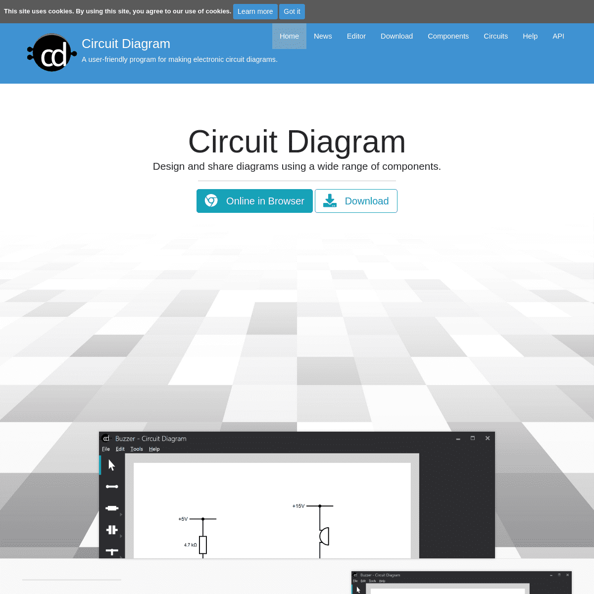
DESIGN AND SHARE DIAGRAMS USING A WIDE RANGE OF COMPONENTS. ------------------------- * __ Online in Browser __ Download -------------------------EASY TO USE
Design diagrams visually by placing components with your cursor. Modify their values using the properties editor. -------------------------EXPORT AS IMAGES
Export your diagrams as images, either SVG or PNG. Plugins are available for additional formats. ------------------------- INCLUDES ALL COMMON COMPONENTS Symbols for most commonly-used components are included, from resistors and capacitors to logic gates and transistors. -------------------------CUSTOM COMPONENTS
Find many more components made by other Circuit Diagram users in the components section . Create your own for ones that haven't been made yet. ------------------------- SHARE CIRCUIT DESIGNS Browse circuits designed by others, and upload your own in thecircuits section .
Contact Statistics Privacy PolicyGitHub © 2019
Circuit Diagram
Details
5